SURGE CAPACITORS
Introduction
Electrical surges from various sources are common occurrences in power systems, including lightning strikes, equipment failures and switching surges characterized by high dv / dt ratios. Hilkar Surge Capacitors are specifically engineered to safeguard the winding insulations of critical equipment such as generators, motors, reactors and transformers.
Surge Capacitors effectively mitigate the impact of over-voltages, offering a cost-effective and adaptable solution. By absorbing energy from Electrical surges, Surge Capacitors shield equipment from damage. Their deployment as surge protection devices markedly reduces both direct and indirect costs associated with equipment repair and business interruptions.
Advantages
- • Save on costs, via reduced downtime and repair costs
- • Improve operational performances, as a result of reduction in production downtime
- • Superior protection against interturn insulation failures
- • More effective protection against rapidly increasing voltages as the response time is shorter than surge arresters
- • Extends lifetime of motors/transformers
- • Reduce the likelihood of pre-strike, re-strike, and re-ignition observed at circuit breakers
- • Ease of installation
- • Low loss dielectric
- • Long lifetime
Application Areas
- • Power Generation
- • Pulp and Paper Industry
- • Petrochemical Industry
- • Chemical Factories
- • Surface and Underground Mining
- • Water and Oil Pumping Stations
- • Railway Applications
- • Large Motors
- • Arc furnaces
- • and many other facilities using any kind of motors and/or transformers
Protections Provided
- • Protection against all practical surge peaks and rise-times
- • Withstands all the motor impulse voltage levels recommended by both CIGRE and IEEE
- • Elimination and damping of multiple pre/re-strike transients that occur during switchgear operation
- • Surge Capacitors are recommended to be used with surge arrester for more comprehensive protection
Product Range
- • Operating Voltage: Up to 36kV
- • Impulse Withstand Voltage: Up to 200 kV BIL
- • Variety of surge capacitance ratings depending on the site requirements and application type (ie, 0.1-0.5 µF)
- • Fully assembled, tested, and ready for interconnection
General Technical Feautures
| Technical Feautures | |||
|---|---|---|---|
| Type | - | Single Phase / Three Phases | |
| Rated Voltage | kV | 1-36 | |
| Rated Frequency | Hz | 50/60 | |
| Capacitance Range | μF | 0.1 - 1 | |
| Capacitance Tolerance | % | -5 / +10 | |
| Incoming Terminal (IEC 60137) | - | Top | |
| Enclosure Protection Degree (IEC 60529) | - | IP00 | |
| Max. Ambient Temperature | °C | ≤ 55 | |
| Cooling | - | Air Natural | |
| Dielectric | - | All-film | |
| Colour | - | Red (Consult to our factory for other colors) | |
| Lightning Arrester | - | Optional | |
Basic Insulation Levels
| BIL | |||||||||
|---|---|---|---|---|---|---|---|---|---|
| Highest voltage for equipment | kV | 2.4 | 3.6 | 7.2 | 12 | 17.5 | 24 | 36 | 52 |
| Rated power-frequency short duration withstand voltage | kV | 8 | 10 | 20 | 28 | 38 | 50 | 70 | 95 |
| Rated lightning impulse withstand voltage (BIL) | kV | 35 | 40 | 60 | 75 | 95 | 125 | 170 | 200 |
Benefits
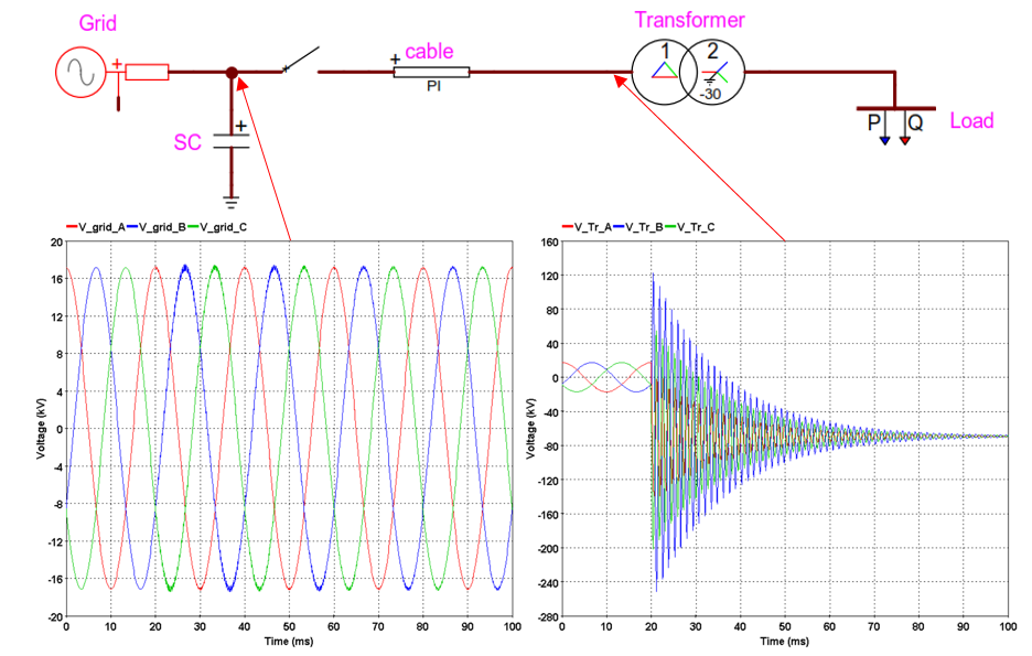
In CASE-1 where the surge capacitor is used for transient voltage waveform steepness and peak reduction at the grid voltage side, the defined withstand voltage limit in the standards are not exceeded and the oscillations in the transient voltage waveform are significantly reduced but the defined withstand voltage limit in the standards are exceeded at the transformer side.

Figure 1 Case-1 @17.5 kV Grid Voltage
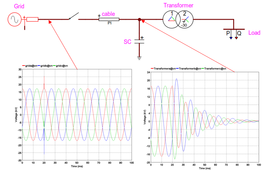
In CASE-2 where the surge capacitor is used for transient voltage waveform steepness and peak reduction on the transformer side, the defined withstand voltage limit in the standards are not exceeded and the oscillations in the transient voltage waveform are significantly reduced, but spikes occur on the grid voltage side.

Figure 2 Case-2 @17.5 kV Grid Voltage
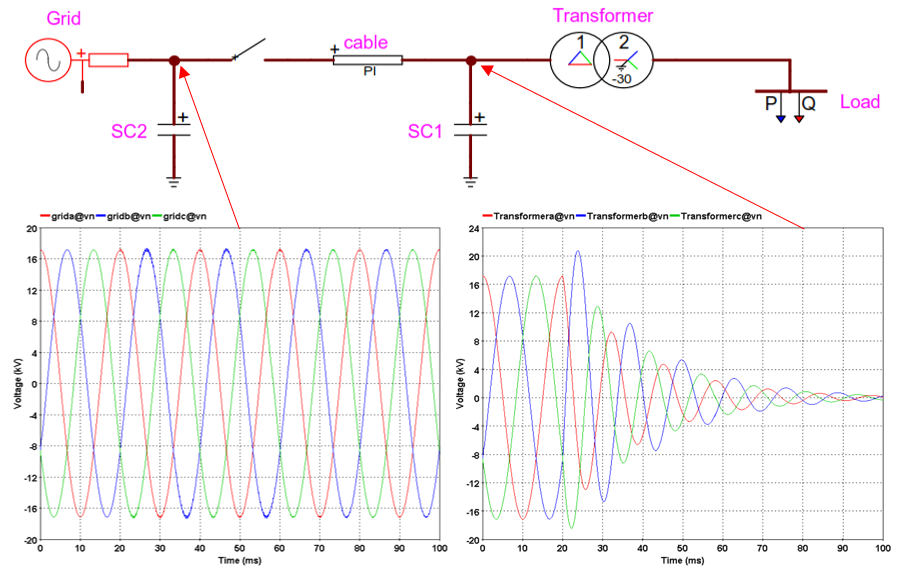
In CASE-3, where the surge capacitor is used for transient voltage waveform steepness and peak reduction at the both (Grid & Transformer) side, the defined withstand voltage limit in the standards are not exceeded and the oscillations in the transient voltage waveform are significantly reduced.

Figure 3 Case-3 @17.5 kV Grid Voltage
Types Available
Surge Capacitors are available as custom designs between 1 to 36 kV and 0.1 to 0.5 F as single or three phase 50/60Hz systems. They are mainly supplied for industrial motor, transformer, reactor and generator protection applications. Single phase and three phase Surge Capacitors manufactured by HILKAR are custom built to meet your requirements. They are used to reduce the magnitude and frequency of transient voltages observed. For requests for lower or higher system voltages please contact factory.

Installation & Commissioning
Hilkar Surge Capacitors are suitable for (but not limited to) installation at the following connection points depending on the application:
- • In the protected equipment’s terminal box or associated switch panel, between each phase to ground.
- • Connection to the equipment terminal box via a minimum of 3x25/16 mm2 cable with the provided accessories.
- • Surge Capacitors must be grounded to the motor/transformer ground or the breaker earth connection.
- • When porcelain bushings are used, connections to the bushings must be through flexible connections so that any shock or vibration that may be transmitted to the bushing during transportation or in service, does not cause any damage.
- • The fixing nuts shall not be tighter than 20 Nm.
- • The flexible leads can be shortened but cannot be extended and must be directly connected to the protected equipment terminals.
Accessories
- • Mounting brackets or clamps
- • Connection cable and flexible leads (optional)


