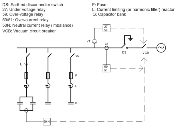
Capacitor Bank Protections
The current of the protection fuses should be selected as If≅2In.
51 relay should be set with a delay for 0.1 seconds between 4-6In (short circuit protection)
50 relay should be set with a delay for 4 seconds for 1.3In (overload protection)
50N relay is recommended to be set with a delay for 4 seconds at the setting of 0.05In (overload protection)
The value of resistor R (kΩ) required to be connected across the capacitor to drop the voltage of the capacitor battery with a capacitance of C (μF) to under 75 V after 10 minutes (600 seconds), can be calculated as below:
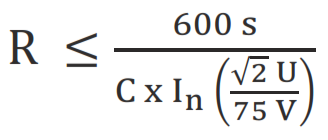
For Delta connection
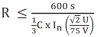
For Star connection
U:System voltage (V)
In: Capacitor nominal current (A)
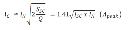
Inrush Current (I_C) Calculation When a Single Battery is Connected to the Circuit
- - U: Phase-Neutral voltage (V)
- - Xc: Phase-Neutral capacitive reactance (Ω)
- - XL: Total inductive reactance between batteries (Ω)
- - Q; Q_1; Q_2: Battery powers (kVAr)
- - S_SC: Short circuit power (kVA) at the point where the capacitors are connected
- - I_N : Nominal current (A_rms) of the battery.
- - I_SC : Short circuit current (A_rms) at the point where the capacitor bank is connected.
The value of the inductor to be connected in series with the capacitor to limit the inrush current down to I_C ≤100I_N:
Example:
Given than:
Q=200 kVAr U=5000 V f-f
S=1000 kVA Z=5%
Inrush current I_C =I_N √(2 S_SC/Q)
I_N=Q/(√3.U)=200/(√3 x5)=23 A_rms
S_SC=S/Z_SC =1000/(5/100)=20.000 kVA
I_C=23√(2 20.000/200)=325 A smaller than 100 x 23 A
Inrush current reactor not required.
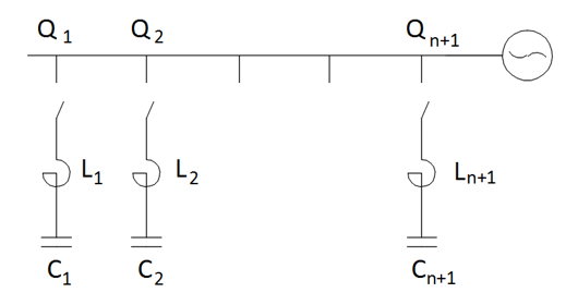
Inrush Current (I_C) Calculation When (n+1) Number of Capacitor Batteries are Connected in Parallel:
When (n) number batteries are energized, (n+1)st step will be energized.
Q (kVAr) : Power of a single step battery
U (kV) : Grid voltage (phase to phase)
ω (rad/s) : 2πf
C (μF) : Capacitance of the capacitor
I (μH/m) : Inductance of bars and cables between the batteries
f_r (Hz) : Resonance frequency
L (μH) : Inrush reactor connected in series to the battery
I_C (A): The peak value of the initial charging current
I_N (A_rms) : Nominal current of the battery
Q =U^2.C.ω= √3.U.I_N
I_C= √(2/3)U.n/(n+1).√(C/I)
f_r=1/(2π√(I.C))
The required reactor to satisfy the expression I_C≤100I_N :
L (μH)=(2.10^6)/3 x Q/(2πf) x (n/(n+1))^2 x 1/((I_C )^2)
If inrush reactor (L) is added,
I_C= √((2 x 10^6)/3 x Q/(2πf) x (n/(n+1))^2 x 1/L)
Example:
For a capacitor bank with 0,5 𝜇H/m inductance, 5 meters height, U=5000 V (phase to phase) with (n+1) = 3 steps, each of which has Q = 200 kVAr power;
- I_N=Q/(√3U)=200/(1.73 x 5) = 23 A_rms
C= √3(U x I_N)/(U^2 x 2πf) = 1,73(23 x 5000)/(5000^2.314)=25,3x10^-6
C=25,3 μF
Inrush current I_C=√(2/3)U x n/(n+1)√(C/I)
- I_C = 0,81 x 5000 x 2/3 √(25,3/(0,5 x 5)) =>
I_C=8589 A_p = 8,59 kA ≥ 100 x 23 A Reactor required!
- Reactor inductance L(𝜇H)
L ≥(2 x 10^6)/3 x (Q.10^(-3))/ω x (n/(n+1))^2 x 1/((I_C )^2)
= 2x10^6 x 0,2/(2π50)(2/3)^2 x 1/(8590)^2 = 7,67 μH
If 50 𝜇H reactor is connected instead of 7,67 𝜇H, then the inrush current will be:
I_C=√(2/3) x 5000 x 2/3 x √(25,3/50) = 1935 A_p
- Resonance frequency f_r = 1/(2π√(L.C))
= 1/(2π√(50 x 10^(-6)x 25,3 x 10^(-6))) = 4475 Hz
Calculations Related to Capacitor Banks:
In capacitors I_max=1,3I_n
- V_max=1.1 V_n - 12 hours / day
- V_max=1.2 V_n - 5 min
- V_max=1.3 V_n - 1 min
When a capacitor bank with a power of Q (kVAr) is connected to a system with a short circuit power of S_sc (kVA), the resonance frequency is:
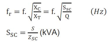
- S: Power (kVA) of the transformer supplying the capacitor
- S_SC: Short circuit power (kVA) of the transformer supplying the capacitor
- Z_SC: Short circuit impedance of the transformer supplying the capacitor (%)
Determining the Q_N of the capacitor required in order to provide a capacitive power of Q_s to a system with a voltage of (U_s):